

Step-by-Step Assembly Guide Released for 24V 314Ah 8S LiFePO4 Energy Storage Battery Pack
Overview
As off-grid solar, RV, marine and small commercial energy storage demand surges, DelGreen has published a complete standardized assembly workflow for its 24V 314Ah 8-series LiFePO4 battery cabinet, offering integrators, DIY installers and factory technicians a fully documented, safety-first construction manual. The 24V 314Ah pack uses eight 3.2V 314Ah prismatic LFP cells in series, delivering 7.99kWh of stable energy storage with integrated intelligent BMS, touch LCD monitor, DC circuit breaker and full insulation hardware. This article breaks down the full professional assembly procedure with critical torque, wiring and insulation standards to guarantee consistent performance and long pack lifespan.
Full List of Standard Assembly Accessories
The complete kit contains all structural, electronic and insulating components required for one finished 24V 314Ah battery unit:
- Metal cabinet housing, front panel, top baffle and mounting brackets
- Dual PCB cell voltage acquisition boards (8S dedicated)
- Industrial-grade BMS protection board with pre-assembled harnesses
- LCD touch display screen with self-adhesive backing
- Yellow epoxy insulation sheets, EVA foam thermal buffer pads
- Copper busbar connectors, copper terminals, fixing bolts
- DC circuit breaker, positive/negative heavy-duty output terminals
- Multi-core cell sampling wires, temperature sensing cables, communication flat cables
- Insulation plastic caps, wiring harness sets and mounting fasteners
Standard Assembly Step-by-Step Workflow
Step 1: Disassemble Cabinet & Sort All Accessories
Remove the cabinet’s top cover, front panel and internal fixing brackets using an electric screwdriver. Take out every component from the packaging and lay them out neatly for inspection, including PCB acquisition boards, BMS, LCD, epoxy insulation plates, foam pads, terminals and wiring kits. Check all PCBs, cables and structural parts for scratches, broken wires or deformation before assembly.

Full accessory kit
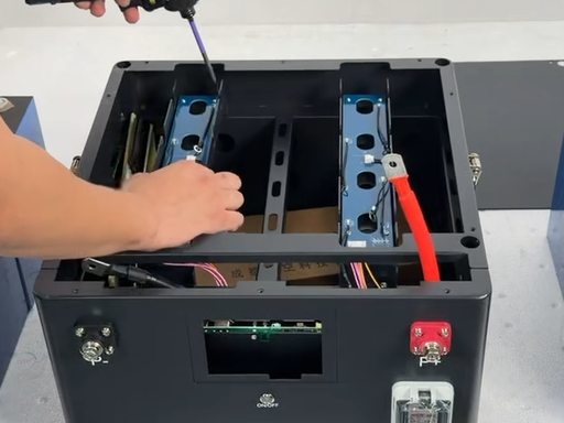
Disassemble cabinet shell
Step 2: Install Internal Epoxy Insulation Boards Inside the Cabinet
Mount yellow epoxy insulation sheets onto the inner walls and partition of the empty metal cabinet. The epoxy board acts as primary electrical isolation between the metal chassis and prismatic cells to prevent short-circuit risks during operation.
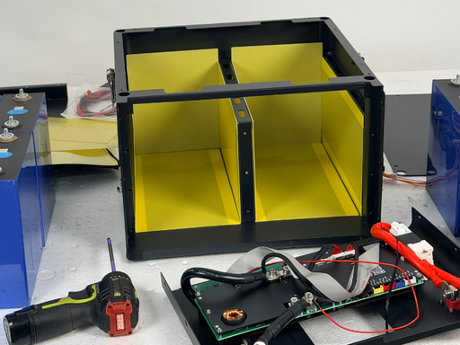
Cabinet lined with epoxy insulation
Step 3: Place 314Ah Prismatic Cells in Sequence with Thermal Foam
Install eight 3.2V 314Ah LFP cells into the cabinet compartment following the cell marking sequence printed on the PCB acquisition boards.
- Stick dual EVA foam pads onto each epoxy sheet; place foam-lined epoxy boards between every two adjacent cells for thermal buffering and insulation.
- Strictly follow the “Cell 1 total negative” marking on the left PCB to align cell polarities correctly to avoid reversed sampling wiring.

Place prismatic cells
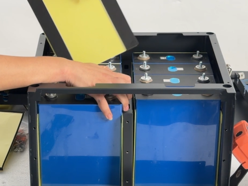
Install foam insulation between cells
Step 4: Secure Front Partition Baffle
Mount the front metal baffle plate onto the cabinet frame and fasten all screws tightly to lock the cells in fixed positions, eliminating cell shifting during transport or vibration.
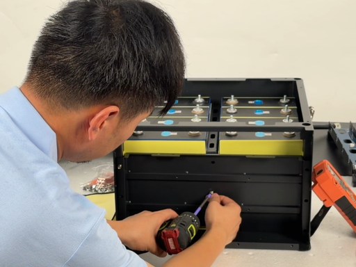
Fix front baffle
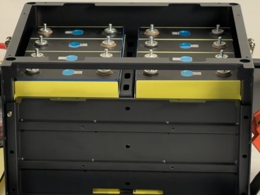
Cell layout after baffle installation
Step 5: Mount Dual 8S PCB Cell Acquisition Boards
Attach pre-cut foam pads to the bottom of the two blue PCB sampling boards for insulation, then screw both boards onto the cabinet above cell terminals. Reference the printed “4th Cell +” polarity label on the PCB to match each cell’s positive/negative terminal perfectly.
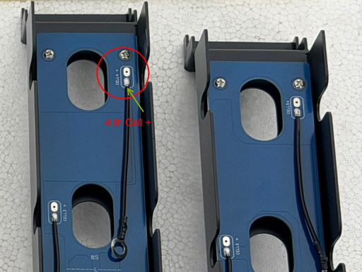
PCB cell marking diagram

Screw down dual PCB boards
Step 6: Install Copper Busbars & Wire Cell Sampling Cables
Fit copper connecting busbars across cell terminals to form the 8S series circuit. Critical rule: Do NOT connect the main total positive and total negative heavy cables at this stage.
- Route individual sampling wires from each PCB to the corresponding cell terminal one-to-one.
- Attach temperature sensing cables to the total negative cell terminal for thermal monitoring by BMS.

Busbar and sampling wiring layout

Completed cell connection
Step 7: Torque Standardization for Terminal Bolts
Tighten all busbar fixing bolts with an electric driver first, then retorque every bolt to a precise 7.5N·m with a digital torque wrench. This standardized torque prevents loose terminals, excessive contact resistance, heat buildup and fire hazards under high current discharge.
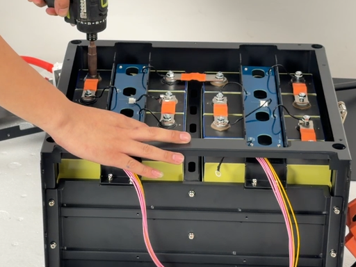
Initial screw tightening
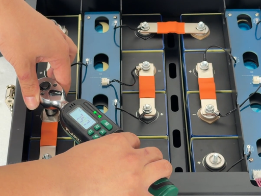
7.5N·m torque calibration
Step 8: Mount LCD Touch Screen on Front Cabinet Panel
The LCD screen comes with strong self-adhesive tape on its back. Install it with extreme care to avoid upside-down placement, which will reverse all screen readouts; once adhered firmly, the screen cannot be repositioned without damage. After aligning the screen to the panel cutout, press evenly to secure full adhesion.
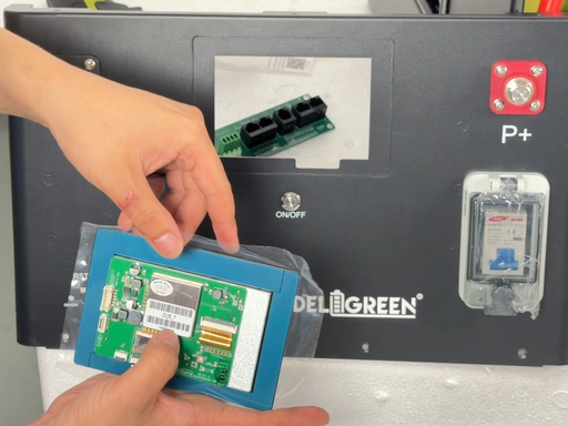
LCD screen inspection
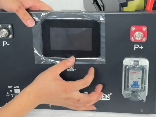
Mount LCD to front panel
Step 9: Assemble BMS, DC Breaker & Communication Sub-Board
The main BMS board arrives pre-wired with power cables and communication harnesses for streamlined assembly:
- Secure the DC circuit breaker to the positive output terminal on the front panel.
- Fix the heavy black main negative cable to the cabinet’s negative terminal post.
- Plug all communication flat cables between the BMS and front interface sub-board as marked by red wiring labels.
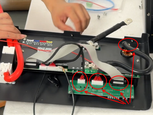
Communication cable wiring diagram
Step 10: Mount the Complete Front Panel Assembly
Attach the finished front panel (pre-fitted with LCD, breaker, positive/negative terminals and communication ports) onto the main cabinet shell and fasten all mounting screws.
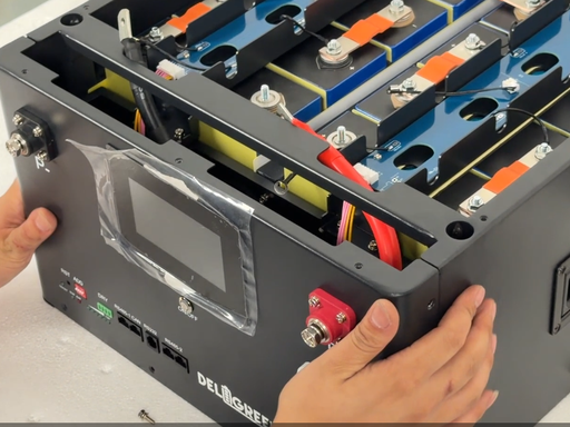
Install full front panel module
Step 11: Connect Main Power Cables (Strict Sequence Required)
Follow this non-negotiable wiring order to avoid short-circuit damage to BMS and PCBs:
- First connect the thick black main negative cable to the first cell’s total negative terminal.
- Second connect the thick red main positive cable, plus the small auxiliary B+ red sensing wire to the final cell’s positive terminal.
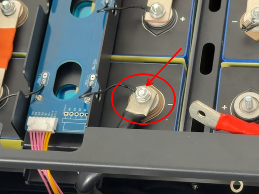
Connect main negative cable
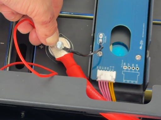
Attach main positive & B+ wire
Step 12: Link PCB Sampling Flat Cables to BMS
Route the two multi-color flat sampling cables from the top PCB boards down to the BMS interface:
- Sampling cable from the left PCB plugs into the white terminal slot on the BMS sub-board.
- Sampling cable from the right PCB plugs into the purple terminal slot on the BMS sub-board.

Sampling flat cable terminal slots
Step 13: Commission & Calibrate via Mobile App
After finishing all mechanical and wiring assembly, power on the battery pack and connect the mobile monitoring APP via Bluetooth:
- Modify core battery parameters on the software: cell series count (8S), rated capacity (314Ah). The factory BMS default value is set to 200Ah and must be updated to match the 314Ah cells to ensure accurate SOC, voltage and capacity readings on the LCD screen.
- Verify real-time cell voltage balance, temperature data and charge/discharge protection thresholds on the touch display before putting the pack into service.
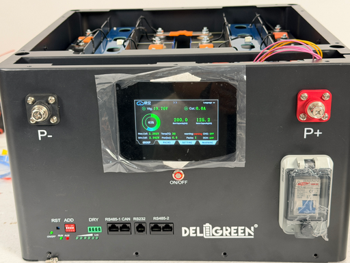
Final powered 24V 314Ah battery pack
Key Safety & Technical Highlights of the 24V 314Ah Pack
- Layered Insulation Design: Epoxy sheets + EVA dual insulation eliminate metal-to-cell contact risks, greatly improving thermal stability under high-load discharge.
- Precision Cell Monitoring: Dual independent 8S PCB sampling boards capture real-time voltage of every single cell, enabling the BMS to execute active balancing and overvoltage/undervoltage protection instantly.
- Standardized Torque Control: Mandatory 7.5N·m torque for all busbar connections eliminates thermal runaway risks caused by loose terminals, a common failure point in DIY lithium packs.
- All-In-One Intelligent Management: Integrated LCD real-time monitoring, DC overcurrent breaker, multi-protocol communication (RS485/CAN) and mobile APP remote parameter adjustment support seamless integration with off-grid solar inverters, RV power systems and microgrid storage equipment.
- High-Capacity 314Ah LFP Cells: 8-series configuration delivers 25.6V nominal voltage, 7.99kWh energy storage, over 6,000 deep charge cycles and excellent low-temperature discharge performance compared to lead-acid alternatives.
Market Application Outlook
This standardized 24V 314Ah LiFePO4 cabinet serves multiple fast-growing energy storage verticals: off-grid residential solar systems, caravan/RV power banks, marine boat energy storage, remote construction site power supply and small commercial backup power. The fully modular, documented assembly process reduces factory production errors and lowers technical barriers for independent battery integrators, accelerating the adoption of safe, high-performance lithium energy storage globally.
About Deligreen Energy Storage Tech
Deligreen specializes in the R&D, manufacturing and technical documentation of integrated LiFePO4 battery cabinets and intelligent BMS solutions for low-voltage energy storage. The company releases standardized assembly guides for all core product lines to support global partners with consistent, reliable battery pack production and post-sales technical training.